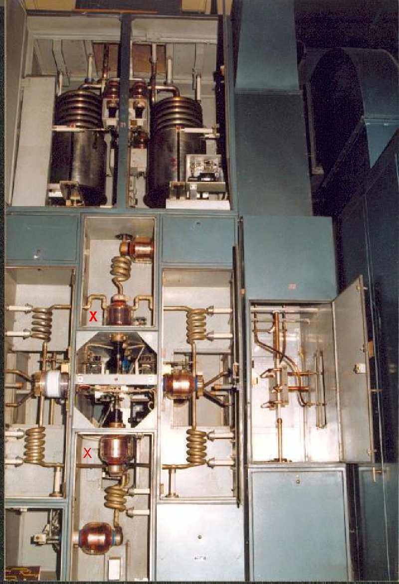
| This is the "L" unit, impedance matching network. This belongs to the "S-7" xtr. On the top are these "little" coils, 4 in total, two in front and two behind. Below are 16 variable capacitors which were moved simultaneously with an only motor, so, they had to be perfectly synchronized. 8 can be seen here and 8 more on the opposite side (mirrored) . This unit was the one that made possible the transmitter could be joined and broadcast 500Kw. Where are the “x”, below left, there are 2 capacitors, one is seen and the other is behind it. |
 |