|
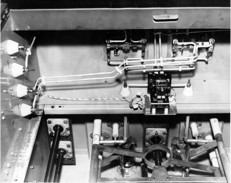
This picture is the internal part of the roof of the driver 8/1. The item which is in the center, is the combined / separate switch, it's to say, in combined the two transmitters were fed by the same driver, in this case, 8/1 & 8/2. Below to the center/right, there is a part of the coupling coil, which was used to feed with more o less power to the transmitter (or transmitters in combined mode). |
 |